Flange terminology is often treated as routine, but it directly affects how reliably a flanged valve will seal once installed. Misunderstanding facing types, pressure classes or gasket selection can lead to leakage or premature failure.
This article outlines the key flange terms as they apply to flanged valves, so that you can specify and install flanged connections with greater confidence and consistency going forward.
What is a Flange in Valve Applications?
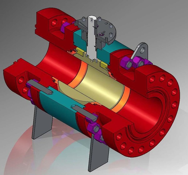
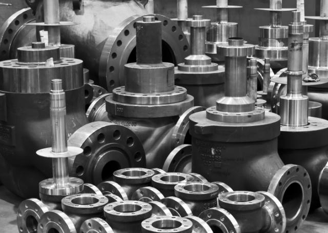
In valve assemblies, a flange is the machined connection point that allows a valve to be bolted into a pipeline. On flanged valves, these are usually integral to the body, forming part of the pressure boundary.
A standard flanged connection consists of:
- A valve flange and a matching pipe flange
- A gasket between the sealing faces
- Stud bolts, nuts and washers to apply load
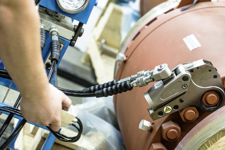
For the joint to seal correctly, bolt load must compress the gasket evenly across aligned faces. Any mismatch in specification or installation will affect that seal.
Flanged Facing Types for Flanged Valves
Facing type determines how sealing load is applied and which gasket can be used. It must match across both mating flanges.
Raised Face (RF)
The most common option for industrial valves. A slightly raised sealing surface concentrates load onto the gasket.
- Typically used with spiral wound gaskets
- Standard across ASME Class 150–600
- Offers consistent sealing across a wide range of pressures
Raised face is widely used because it delivers reliable gasket compression without excessive bolt load.
Flat Face (FF)
Flat face flanges sit flush across the entire surface, with no raised area.
- Used with full-face gaskets
- Common in cast iron systems
- Reduces the risk of flange damage under load
Flat face connections rely on even bolt tightening, as load is spread across the full face.
Ring Type Joint (RTJ)
Designed for high-pressure service, RTJ flanges use a machined groove and metal ring gasket.
- Typically ASME Class 600 and above
- Forms a metal-to-metal seal under compression
- Used in critical applications such as oil and gas
RTJ connections require precise machining and careful installation, but provide very high sealing integrity.
Common Flange and Connection Types
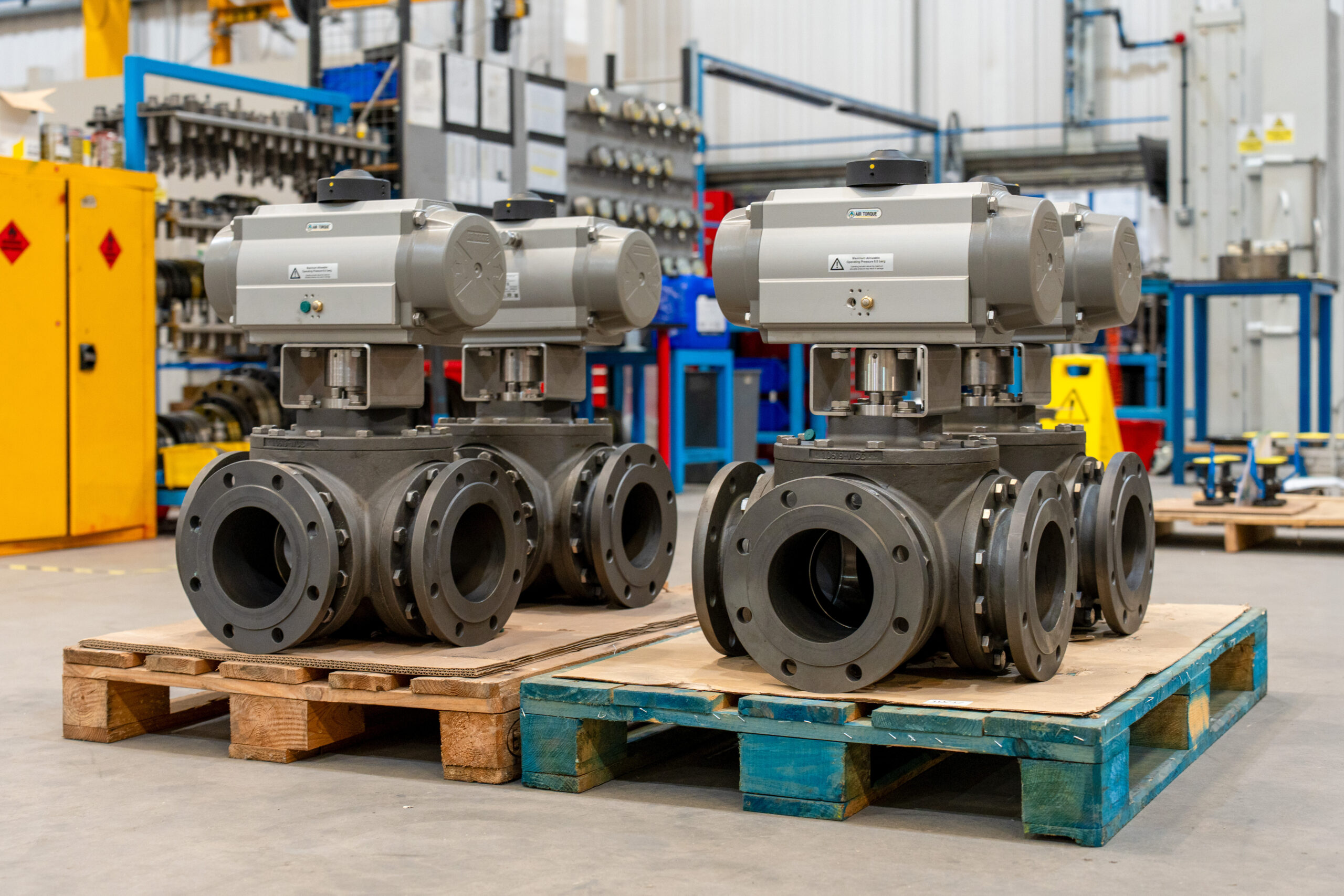
Connection type determines how the valve is installed and how loads are transferred into the pipework.
Weld Neck (WN)
Weld neck flanges are butt-welded to the pipe, with a tapered hub that improves stress distribution. They are typically used in high-pressure or cyclic service where fatigue resistance matters.
Slip-on (SO)
SO flanged slide over the pipe and are secured with fillet welds. They are easier to align during installation, but are generally limited to lower pressure systems.
Blind (BL)
Blind flanges are used to close the end of a pipeline or nozzle. They must be designed to withstand full system pressure, as they do not benefit from pressure balancing.
Socket (SW)
Socket weld (SW) flanges are used mainly on small bore pipework. The pipe sits inside a recessed socket before welding, which helps with alignment and strength in higher pressure service.
Threaded (TH)
Threaded (TH) flanges are screwed onto threaded pipe and do not require welding. They are typically reserved for lower pressure systems due to the potential for leakage along the threads.
Lap Joint (LJ)
Lap joint (LJ) assemblies use a stub end with a loose backing flange. This allows rotation for easier alignment, particularly in systems where frequent dismantling is required.
Each type affects not only installation, but also how the joint responds to stress over time.
Pressure Ratings (Flange Class)
Flange class defines the pressure-temperature capability of the connection.
Common ASME classes include 150, 300, 600, 900, 1500 and 2500. As the class increases, so does the required material thickness and bolt load needed to maintain a seal.
The key point is consistency – the valve flange rating must match the pipeline to avoid overstressing the joint or compromising sealing performance.
Flange Standards
Standardisation ensures that flanged valves align with mating pipework. Key standards include:
- ASME B16.5 / B16.47 – Inch-based dimensions and ratings
- EN 1092-1 – Metric flange system used across Europe
- API standards – Additional requirements for oil and gas
Mixing standards without checking compatibility can lead to misalignment or sealing issues.
Gaskets
The gasket provides the seal within the flanged joint and must suit both the facing type and service conditions.
- Spiral wound gaskets – Used with raised face flanges, combining metal windings with a soft filler
- RTJ gaskets – Solid metal rings for RTJ grooves
- Full-face gaskets – Used with flat face flanges
Material choice depends on temperature and pressure, as well as the media being handled.
Why Flange Terminology Matters
Correct flange specification ensures the valve, gasket and pipework work together as intended. Even small inconsistencies in terminology or selection can affect alignment and sealing performance, particularly once a system is in operation.
Understanding these terms provides a clearer basis for specifying and assessing flanged valves. If you need support applying this in practice, our team at ACV Group can offer guidance on suitable configurations and supply appropriate valve solutions.